A long-standing issue in the ZynqMP users community has been the loading of a PMU firmware configuration object when U-Boot SPL is used. A recent patch to U-Boot addresses the problem at its root.
The “configuration object”
The Platform Management Unit (PMU) needs a configuration object to know how to operate the SoC: which power domains to enable, which peripherals should be accessible by each CPU core, etc.
A configuration object is produced by the Xilinx tools in the form of a C file (pm_cfg_obj.c), which contains values to be passed at runtime to the PMU firmware. It is design-specific, so it has to be regenerated when the design is modified.
The Xilinx workflow: FSBL
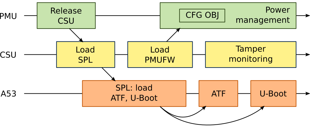
When using the workflow supported by Xilinx, the Xilinx FSBL (First Stage Bootloader) has a role similar to the U-Boot SPL: initializing DDR an other low-level setups, then loading ATF and U-Boot proper. FSBL is generated with a built-in configuration object, and passes it to the PMUFW at runtime before jumping to ATF and U-Boot proper.

The Community workflow: U-Boot SPL
Many users prefer using U-Boot SPL over the Xilinx FSBL. So far these users had to face a problem: there is no code in U-Boot to load the configuration object in the PMU firmware.
The best workaround for U-Boot SPL users is to apply a patch to the PMUFW itself to have the configuration object built-in and self-load it. This approach works but has drawbacks: among others, it forces to use a different PMUFW binary for each hardware and hardware configuration. It also makes it impossible to change the configuration after boot.
More troubles with meta-xilinx
The mentioned patch has never been included in the meta-xilinx Yocto layer. Many newcomers of ZynqMP have downloaded meta-xilinx, followed its instructions and come up with a non-booting board. They have had a hard time in discovering they need to patch the pmu-firmware in their own layer to be able to boot.
The problem got worse with the Yocto 2.6 (Thud) version of meta-xilinx. In previous versions there was a hack to build a (Microblaze) PMU firmware within an ARM64 build. That hack has been removed from meta-xilinx Thud and replaced with a multiconfig-based setup. Now there are two different configurations: a Microblaze one to build the PMU firmware and an ARM64 one to build all the rest.
This has been a good cleanup, but with an unwanted side-effect: now it is impossible to build two different PMU firmware binaries for two different MACHINEs.
Solving the problem at its root
These increasing difficulties triggered me to try and solve the problem at its very root: the inability of U-Boot SPL to load the configuration object into the PMU firmware at runtime, like the FSBL does.
And it turned out not to be that complex in the end. The communication between the ARM core where SPL runs and the PMU happens via a mailbox. I studied the protocol mostly in the FSBL and ARM Trusted Firmware source code and came up with a simple implementation that is enough for the SPL needs. SPL then uses the mailbox in board_init() to send the configuration object to the PMU firmware.

With these changes U-Boot SPL now behaves like FSBL. No need to patch PMU firmware anymore!
With this feature in U-Boot SPL there is no more need for a different PMU firmware binary for each different board configuration. A single PMU firmware binary image can be used to boot any ZynqMP board. Only U-Boot SPL will need to be rebuilt to use a different configuration object. Patching the PMU firmware to hard-code its configuration will not be needed anymore.
Mainlining
I sent a patch with this new feature to the U-Boot mailing list. It took a few iterations to have it in a good shape, and finally the maintainer Michal Simek accepted it at its fifth iterations a few days ago. It should be merged in mainline U-Boot version 2019.10.
Using this new booting process is simple: just set the ZYNQMP_SPL_PM_CFG_OBJ_FILE configuration variable to the location of your configuration object. It will be automatically linked in U-Boot SPL and loaded during board initialization. Leaving the variable empty will leave the old behavior, which can still be used as before.
However note that the configuration object file must be in binary format. The C file produced by the Xilinx tools is not directly usable by U-Boot SPL. In order to convert the file to the proper format I also wrote a tool that automates the process. A patch adding this tool to U-Boot has been accepted together with the first one.
Together these two patches will allow a better booting process for ZynqMP users wanting to use U-Boot SPL, automating the whole building process in their buildsystem from mainline U-Boot and their pm_cfg_obj.c file to bootable images.
Hi Luca,
Thank you for the in depth analysis and patch for U-boot! Been trying to figure something like this out for a while but I’m glad you’ve fixed the root issue. I’ve been struggling with Xilinx’s tools lately and it’s funny how the FOSS community is more helpful than Xilinx ever could/would be
Quick question; do you still recommend using Xilinxs official U-boot fork? It looks like they’ve also merged your changes into it but I’d prefer to use the main project.
Hi Andrew,
thanks for your appreciation.
For a new project using the community workflow I would try mainline U-Boot first. It probably still lacks some drivers and features, but if it has support for the devices you need for booting, than it should be enough. If it only lacks one or two simple ones you can try to port them from the Xilinx fork. Only if that turns out to be too hard I’d switch to Xilinx U-Boot.
Also I’d use the latest master branch from mainline U-Boot, to catch even the most recent improvements.
Asking on the U-Boot mailing list would also be a good idea. Mention the devices you need along with any non-obvious needs you have. People there knows if your needs are already covered or not.
Luca
So I’ve been trying to understand how to build spl, u-boot and the config object. I feel like I should use the zynqmp-pmufw-builder without doing the patch step. It is also worth trying to boot the embeddsw repo has to something newer than 2018.3/ Does this sound like the write thing to do?
Hi Philip,
you got it, the patch step is not needed anymore as you can have the config object loaded by U-Boot SPL.
Unfortunately I haven’t been working on this project recently so it got a bit outdated. Should it not work on modern embeddedsw versions I’d be glad to receive patches to get it up-to-date.
And yes, unless there are better tools around nowadays, I’d preferably go for the u-boot + SPL + PMUFW boot scheme.
Hi Luca
Since your patch is already on u-boot, I understand that the example board that you committed to buildroot, zynqmp_zcu106, could be upgraded so as not to use the prebuilt PMUFW image on your github but instead use only u-boot? I don’t think I’ve completely understand all about the ZynqMP booting system :/
Thanks!
Hi Alvaro,
first: don’t worry if you still don’t understand completely the ZynqMP booting system, it’s very complex.
Regarding your question: with current mainline U-Boot you still need a PMUFW binary. The patch that I sent allows to use a PMUFW without a configuration object hard-coded and have the configuration object loaded into PMUFW by U-Boot SPL. In other words you could use one of the generic pmufw images (pmufw-v2018.3.bin) instead of one of the board-specific ones (pmufw-zcu106-default-v2017.4.bin) from my zynqmp-pmufw-binaries repo.
Actually the Buildroot defconfig could be upgraded to do that.
Luca
Hey Luca,
I’m trying to get this working on a new board, using the new process you mentioned in a previous post, and I’m struggling to get ANY output from the board during boot.
Is this the updated process (adapted from https://u-boot.readthedocs.io/en/latest/board/xilinx/zynqmp.html)?
1) Build bl31.bin
– Using official ARM Trusted Firmware repo v2.2
– PLAT=zynqmp
2) Produce PMU FW
– Either make a new one using XilinxSDK/Vitis or use one of your premade .bin files
– Produce pm_cfg_obj.c in XilinxSDK/Vitis and either embed the object in the firmware, pass the object to Uboot, or pass the actual .c file to Uboot
3) Build Uboot
– Currently using mainline, master commit
– Pass bl31.bin path via command line BL31=/bl31.bin
– Pass PMU firmware via CONFIG_PMUFW_INIT_FILE
– (Optionally, if not embeded) pass the PMU configuration object or c file via CONFIG_ZYNQMP_SPL_PM_CFG_OBJ_FILE
4) Make bootable SD image (specific files will vary by configuration)
– At a minimum boot.bin (which contains the PMUFW?) and u-boot.bin
– May or may not need u-boot.itb instead of u-boot.bin. The uboot docs say the itb file contains the ATF code. I’ve tried both u-boot.bin and u-boot.itb without success.
Thanks,
Jay
Hi Jay,
I have never used the instructions from the U-Boot docs that you pointed to, but they are most likely OK.
The “I see nothing on UART” is unfortunately a common problem, and it gives no hint on where the problem is… I can share some generic suggestions for troubleshooting that have been helpful to other people in the past.
Have a look here, somebody recently sent a patch to support a board in Buildroot and you might find interesting tips:
Good luck!
Thanks Luca,
I do have this working now. A factory default image worked fine, so I started working backwards a bit. I think your first bullet was spot on. I think the issue was with the uart port. My issue appears to have been a problem with either the DTS, the board files like stuff in ‘include/configs’, or maybe the ps init files. I found a decent example online for the board I’m working with that just needed some tweaking, and now I patch that into uboot v2021.04
It does seem that the steps I listed are basically correct. And yeah, it seems you need to use u-boot.itb, or atf-uboot.bin. The uboot SPL will basically tell you as much during startup, since it seems to look for one of those to exist on the boot partitions.
I am actually using buildroot. I recently updated to the latest version in order to get some of the new uboot patches as buildroot recently bumped the uboot version.
After that a lot of the default settings have worked. The only things I’ve found odd so far were that uboot no longer loads uEnv.txt by default, wont load uboot.env, and there is no sdboot command defined even though its referenced in the default environment. These problems aren’t really a big deal though.
The bigger problem I’m currently having is a kernel panic which seems to be a common on the Xilinx forums. All the existing solutions have mentioned having an error in the DTS for the szie of the ram. I’ve double checked this and don’t seem to have that problem.
ZynqMP-IOCC> setenv sdboot ‘ \
> setenv devicetree_load_address 0x02000000 && \
> setenv ramdisk_load_address 0x04000000 && \
> setenv kernel_load_address 0x02080000 && \
> fatload mmc 0 ${kernel_load_address} Image && \
> fatload mmc 0 ${devicetree_load_address} devicetree.dtb && \
> fatload mmc 0 ${ramdisk_load_address} uramdisk.image.gz && \
> booti ${kernel_load_address} ${ramdisk_load_address} ${devicetree_load_address}’
ZynqMP-IOCC> boot
24691200 bytes read in 1646 ms (14.3 MiB/s)
30571 bytes read in 17 ms (1.7 MiB/s)
55033112 bytes read in 3664 ms (14.3 MiB/s)
## Loading init Ramdisk from Legacy Image at 04000000 …
Image Name:
Image Type: AArch64 Linux RAMDisk Image (uncompressed)
Data Size: 55033048 Bytes = 52.5 MiB
Load Address: 00000000
Entry Point: 00000000
Verifying Checksum … OK
## Flattened Device Tree blob at 02000000
Booting using the fdt blob at 0x2000000
Loading Ramdisk to 7aa86000, end 7df01cd8 … OK
Loading Device Tree to 000000007aa7b000, end 000000007aa8576a … OK
Starting kernel …
[ 0.000000][ T0] Booting Linux on physical CPU 0x0000000000 [0x410fd034]
[ 0.000000][ T0] Linux version 5.4.0-xilinx (user@user-VirtualBox) (gcc version 8.4.0 (Buildroot 2021.05.1)) #7 SMP PREEMPT Sat Aug 21 13:55:47 EDT 2021
[ 0.000000][ T0] Machine model: Avnet Ultrazed IOCC
[ 0.000000][ T0] earlycon: cdns0 at MMIO 0x00000000ff000000 (options ‘115200n8’)
[ 0.000000][ T0] printk: bootconsole [cdns0] enabled
[ 0.000000][ T0] efi: Getting EFI parameters from FDT:
[ 0.000000][ T0] efi: UEFI not found.
[ 0.000000][ T0] cma: Reserved 256 MiB at 0x000000006a800000
[ 0.000000][ T0] psci: probing for conduit method from DT.
[ 0.000000][ T0] Internal error: Oops – BUG: 0 [#1] PREEMPT SMP
[ 0.000000][ T0] Modules linked in:
[ 0.000000][ T0] CPU: 0 PID: 0 Comm: swapper Not tainted 5.4.0-xilinx #7
[ 0.000000][ T0] Hardware name: Avnet Ultrazed IOCC (DT)
[ 0.000000][ T0] pstate: 00000085 (nzcv daIf -PAN -UAO)
[ 0.000000][ T0] pc : do_undefinstr+0x168/0x1c8
[ 0.000000][ T0] lr : do_undefinstr+0x8c/0x1c8
[ 0.000000][ T0] sp : ffffffc0116a3c70
[ 0.000000][ T0] x29: ffffffc0116a3c70 x28: ffffffc0116b1980
[ 0.000000][ T0] x27: 0000000081000200 x26: ffffffc0114bb6de
[ 0.000000][ T0] x25: ffffffc0116a8880 x24: 0000000000000000
[ 0.000000][ T0] x23: ffffffc0116a8848 x22: ffffffc0116a3cc0
[ 0.000000][ T0] x21: 0000000000000000 x20: ffffffc011810100
[ 0.000000][ T0] x19: 00000000d4000003 x18: 0000000000000000
[ 0.000000][ T0] x17: 00000000208c43a0 x16: 0000000000000013
[ 0.000000][ T0] x15: 000000000000000a x14: ffffffffffffffff
[ 0.000000][ T0] x13: 0000000000000018 x12: 0101010101010101
[ 0.000000][ T0] x11: 0000000000000004 x10: 0101010101010101
[ 0.000000][ T0] x9 : fffffffffffffffc x8 : 0000000000000008
[ 0.000000][ T0] x7 : ffffffc01181010c x6 : 0000000000000000
[ 0.000000][ T0] x5 : 0000000000000000 x4 : 0000000000000000
[ 0.000000][ T0] x3 : ffffffc0116b3488 x2 : 0000000000000000
[ 0.000000][ T0] x1 : ffffffc0116b1980 x0 : 0000000000000085
[ 0.000000][ T0] Call trace:
[ 0.000000][ T0] do_undefinstr+0x168/0x1c8
[ 0.000000][ T0] el1_undef+0x10/0x84
[ 0.000000][ T0] __arm_smccc_smc+0x0/0x2c
[ 0.000000][ T0] psci_get_version+0x24/0x2c
[ 0.000000][ T0] psci_0_2_init+0x20/0x2a8
[ 0.000000][ T0] psci_dt_init+0x74/0x94
[ 0.000000][ T0] setup_arch+0x324/0x570
[ 0.000000][ T0] start_kernel+0x8c/0x428
[ 0.000000][ T0] Code: 34fff801 f94086c0 f2400c1f 540001e0 (d4210000)
[ 0.000000][ T0] random: get_random_bytes called from init_oops_id+0x24/0x40 with crng_init=0
[ 0.000000][ T0] —[ end trace 0000000000000000 ]—
[ 0.000000][ T0] Kernel panic – not syncing: Attempted to kill the idle task!
[ 0.000000][ T0] —[ end Kernel panic – not syncing: Attempted to kill the idle task! ]—
I think the issue above might be related to not having the PL portion configured. When I tried flashing the FPGA from uboot I was getting errors. I decided to look into the execution level a bit and realized that uboot wasn’t actually entering the ATF, it was complaining about a missing file. That file, atf-boot.ub, was not missing but it seems I had to turn on legacy image support to use it. Or pehaps it was CONFIG_SPL_ATF_LOAD_IMAGE_V2, I’m still checking that.
It now tries to boot into the ATF but fails:
Debug uart enabled
U-Boot SPL 2021.04 (Aug 22 2021 – 09:37:18 -0400)
PMUFW: v1.1
Silicon version: 3
EL Level: EL3
Multiboot: 0
Trying to boot from MMC2
NOTICE: ATF running on XCZU3EG/silicon v4/RTL5.1 at 0xfffea000
NOTICE: BL31: Secure code at 0x60000000
NOTICE: BL31: Non secure code at 0x8000000
NOTICE: BL31: v2.4(release):release_0_4-65-g10306ff-dirty
NOTICE: BL31: Built : 09:15:55, Aug 22 2021
initcall sequence 000000000807cae8 failed at call 000000000804bf28 (err=-19)
### ERROR ### Please RESET the board ###
The error above was caused by not having the right pm_cfg_obj.c file being given to uboot.
Fixing that, along with either the legacy image support and/or CONFIG_SPL_ATF_LOAD_IMAGE_V2, got uboot to enter the ATF and run in EL2 as opposed to EL3.
My linux kernel still hangs during boot, but now without a kernel panic. Not sure if this is progress or not.
While what I said below was true, uboot wasnt going to EL2 indicating that the ATF wasn’t right, it also turns out you need to use the xilinx ATF gitrepo, not mainline, otherwise you’ll get all sorts of errors during boot when linux goes to add devices.
Thanks for sharing your findings Jay.
In other circumstances the mainline ATF works fine, as the ZCU102 support in Buildroot (https://git.busybox.net/buildroot/tree/configs/zynqmp_zcu106_defconfig?h=2021.08-rc2#n17).
Perhaps you need support for some feature that Xilinx has not yet mainlined. Unfortunately the cap between mainline ATF and Xilinx ATF seems still relevant:
$ git diff –shortstat v2.2 xilinx_rebase_v2.2_2020.2
63 files changed, 4424 insertions(+), 845 deletions(-)
$
This proves once again that mixing and matching different versions of the various boot-related components can lead to errors that are hard to diagnose. When possible, starting from a known-working set of components and then changing them one by one is usually a better way to proceed wasting less time.
Thanks for the post! A dumb question: What are the advantages of using U-boot SPL over Xilinx FSBL?
Hi Alper, I’m glad you appreciated my post.
Choosing U-Boot SPL or FSBL is partly a personal choice.
One reason I prefer SPL is: “do not reinvent the wheel”. U-Boot SPL is used in many other embedded systems, virtually wherever U-Boot is used. This allows embedded engineers to reuse their knowledge (and their code) across different projects and have fewer differences across products based on different SoCs. Vendor-specific software forces to reinvent the wheel for each platform.
Another reason is related to tools. Building FSBL normally requires Vitis (formerly called XSDK), which is a huge tool especially if compared to the tiny code size of a bootloader. It is proprietary, which is something not everybody likes in the open source world as you cannot know how it works, fix and improve it as you can do with the other components and tools.
Practically speaking, using Vitis/XSDK to build FSBL can not be automated in a clean way within an embedded build system such as Yocto or Buildroot. This is a big obstacle if you want the maximum number of users to be able to build images for a given embedded system. For example people can just download Buildroot and compile a defconfig for the Xilinx ZCU106 board in minutes, as it uses U-Boot SPL. If it were based on FSBL users would first have to install Vitis, and it would be needed on any continuous integration machine. And if you want to build no a non-x86 machine or non-Linux and non-Windows OS you’re out in the cold. Imagine to multiply this for every silicon vendor!
Overall, switching from FSBL to SPL makes the entire workflow closer to the typical workflows used in embedded Linux systems.
It’s worth mentioning that SPL used to boot way faster than FSBL, especially when it has to load an FPGA bitstream. However FSBL has improved its boot time in recent years so this reason does not apply anymore.
I hope I answered your question and that whichever bootloader you choose it will the best for you!
Luca
I got it. Thank you very much for the detailed answer and the discussion!
Hi Luca,
I’m involved in a project using ZYNQ UltraScale + MPSoC architecture. Cortex®-A53 is used for SW application on a baremetal environment. Also, PSCI v1.1 is used.
We’re able to get a node to be managed, get the status for the different nodes in the system, but when we try to force powerdown or suspend a node after retrieving it with Access control, the result is that specific node does not change it current status and does not powerdown or suspend in consecuence.
After huge investigation we have found that a possible way to face this is by creating a FSBL image with the nodes to be powered down or suspended depicted as slaves. We’re doing this by including the slave we want to suspend or powerdown in section Prealloc in the pm_cfg_obj.c file but we’re not sure if this is the right direction to success on this task.
For example, we want to power down unused devices such as Ethernet controllers, SATA, USB, RPUs, etc in order to reduce power consumption and thus the board temperature if it gets too high. We are not able to do this this through force powerdown API, and we are not sure if it is a matter of PMU configuration object loaded by the FSBL or maybe some slaves cannot be powered down and we have to use another API.
Thanks in advance.
Hello Rober,
thank you for your comment!
I’m afraid I have no experience in bare metal development on zynqmp, but definitely you should pass a PMU configuration object to the PMU firmware, otherwise it won’t have any idea of how your system is configured.
The only way to generate one, as far as I know, is to create a Vivado project for your part, configure all the peripherals to at least enable the ones you want to use and disable the others, and generate an XSA project file. Vitis can then be used to generate the pm_cfg_obj.c from the XSA file. There can be other ways but none that is supported by Xilinx, abd I definitely don’t know one.
Hi Luca,
Thank you very much for you clear explanation. Currently I am migrating from a 3 year old u-boot with FSBL workflow (not handy for real world scenarios) to the FOSS approach as you described. I am using your latest generic PMU binary.
Currenlty I am not able to get any UART output from the SPL. The most obvious is the UART configuration, which leads me to a few questions. U was unable to find find an answer to this, I was hoping you could give me some direction.
The board uses MIO38/MIO39 for UART0. It seems most other boards use MIO18/MIO19, so a wrong MUX config seems obvious.
A kind of default u-boot configuration is “xilinx_zynqmp_virt_defconfig”
However this configuration is configured to remove the pinctrl node from the SPL devicetree. Of course this can be changed, but I was wondering if the UART I/O MUX for the SPL is normally configured in another way (e.g. board setup code or via the PMU)
In the pinctrl definition is also a ‘group’ (e.g. groups = “uart0_4_grp”)
I could not find any info, which explains how to obtain the group and what it is doing. I assume it is related to the number PINMUX configurations for a peripheral. So in case of UART0 group 0 refers to using MIO 2/3, group 1 to
using MIO6/MIO7. That would result in MIO18/19 for group 4, which matches some configurations I have seen.
This is just an assumption, but I was unable to find info which confirms it.
It would be appreciated if you could give a few pointers.
Thanks,
Marcel
Hello Marcel,
thanks for you appreciation!
I’m afraid I’m very up to date on recent zynqmp development. However based on a quick code inspection of mainline U-Boot it looks like things haven’t changed much with respect to pinmuxing. In this case, most of the pinmuxing is done in SPL (or FSBL) by the code in psu_init_gpl.c. This file contains a long list or register writes that set pinmuxes and other chip settings. It is automatically generated by Vivado based on the settings in the “Zynq Ultrascale+ MPSoC” block in the IP integrator. You should generate one and set XILINX_PS_INIT_FILE in U-Boot to use it.
I hope this helps
Luca
Hi Luca – Thank you for doing this work. One thing I don’t understand is how the hardware is specified for the pmu.bin file that your zynqmp-pmufw-builder tool builds.
For example, how do I specify building the pmu.bin for a ZCU102 vs a ZCU106. Or even more so, how do I specify what hardware (e.g. additional USB ports, etc) that a custom board might use?
Hi Terence,
thanks for your appreciation!
The PMU firmware itself is generic and works on any zynqmp board with any configuration. It knows about your hardware at runtime by reading the configuration object. The configuration object is generated by Xilinx Vitis based on the hardware definition as prepared with Vivado.
With the old community workflow (before U-Boot 2019.10) you had to hardcode the configuration object into the PMU firmware itself.
With U-Boot 2019 and later this is not needed: you can now link the configuration object into U-Boot SPL, which hands it to the PMU firmware.
I hope this clarifies your doubts.
Luca
Hi Luca – Thanks so much for the reply! By “hardware definition” you mean exporting the XSA file from Vivado, right?
But it is unclear to me what the “configuration object” is and how to generate it using Vitis. Could you explain?
Also, is there any documentation on how to link the configuration object in? I would think when building pmu.bin using zynqmp-pmufw-builder this would need to be done but I’m not sure how.
Thanks again.
Hi Luca – Since my last response I realized you defined “configuration object” at the top of the blog post as this file: pm_cfg_obj.c – Sorry, I forgot this since last reading yesterday.
So, this is making more sense. However, I noticed on the github readme it says that copying in a pm_cfg_obj.c is deprecated?
If so, I’m not sure how my pm_cfg_obj.c is built into pmu.bin.
Hi Terence,
you are just not supposed to link the configuration object (which is pm_cfg_obj.c indeed) into the pmufw.bin anymore.
You should now link it into U-Boot SPL instead. This can be done in two steps:
Should that appear weird, think about your e-mail client, that you have configured with your settings. You haven’t recompiled it with your settings built-in, right? You use a standard program which reads your settings from a file. Similarly, the PMU firmware is a generic program for every zynqmp SoC, and the configuration object is a configuration data that it reads at runtime to know how it should configure the chip. Except it is passed by U-Boot SPL (or the Xilinx FSBL) using a different technique. No need to compile a different PMU firmware for each board.
I hope this clarifies.
Luca
Thank you, Luca. After reading your latest reply, reviewing your blog post, and looking though U-Boot this now makes perfect sense.
I’ve done as explained above, converting pm_cfg_obj.c into a binary file using the zynqmp_pm_cfg_obj_convert.py tool and setting ZYNQMP_SPL_PM_CFG_OBJ_FILE appropriately.
It’s partially booting but I’m running into some other problems which I don’t think are directly related to this process. I’m currently investigating…
Thank you for doing this project and for such good support and explanations. I really appreciate it.
-Terence
Hi Terence,
thank you for providing your feedback.
Enjoy your hacking!
Luca
Hi Luca – Just a follow up question: I see the pmufw.bin is used by the Xilinx Zynq MPSoC Firmware layer (zynqmp.c ) driver in Linux.
I’m to trying to setup 1G ethernet on a custom board that has a ZynqMP and getting the following errors at bootup from the Linux kernel:
macb ff0b0000.ethernet: error -EACCES: failed to add to PM domain domain4
macb: probe of ff0b0000.ethernet failed with error -13
When debugging the code I see that zynqmp.c makes a call into the pmufw.bin which is returning the Xilinx error code XST_PM_NO_ACCESS which has this description: “The processing cluster does not have access to the requested node or operation”.
I’m stumped on the cause of this issue and thought I’d ask you if you’d ever seen it before or knew where I should look in the firmware to resolve the issue. Any idea?
Hello Terence,
first of all you should check your pm_cfg_obj.c: is the Ethernet adapter you are trying to use enabled in there? To discover it, look for the
NODE_ETH_0…MODE_ETH_3labels; you sould see a sections like this:NODE_ETH_0, PM_SLAVE_FLAG_IS_SHAREABLE, PM_CONFIG_IPI_PSU_CORTEXA53_0_MASK| PM_CONFIG_IPI_PSU_CORTEXR5_0_MASK| PM_CONFIG_IPI_PSU_CORTEXR5_1_MASK, /* IPI Mask */If the last line looks like
0U, /* IPI Mask */, then it is not enabled so you should go back to your Vitis design and enable it.I hope this helps.
Luca
Hi Luca, thanks for the quick reply, yes, I do have the following in my pm_cfg_obj.c which appears to match what you showed.
“`
NODE_ETH_0,
PM_SLAVE_FLAG_IS_SHAREABLE,
PM_CONFIG_IPI_PSU_CORTEXA53_0_MASK | PM_CONFIG_IPI_PSU_CORTEXR5_0_MASK | PM_CONFIG_IPI_PSU_CORTEXR5_1_MASK, /* IPI Mask */
NODE_ETH_1,
PM_SLAVE_FLAG_IS_SHAREABLE,
0U, /* IPI Mask */
NODE_ETH_2,
PM_SLAVE_FLAG_IS_SHAREABLE,
0U, /* IPI Mask */
NODE_ETH_3,
PM_SLAVE_FLAG_IS_SHAREABLE,
0U, /* IPI Mask */
“`
Any other ideas?